So i've been using blender(instead of Maya, which I'm more comfortable with) to model this intricate motorcycle from Piaggio. The X8 scooter. Truth be told, I'm a motorcycle guy rather than a car guy.
Here are the final product photos:
If you're interested in the process, read further:
"I first started with, as usual, reference images, if there are blueprints, then all the more better." -Wych
(images lifted from various places. Credits fully to them. I dont own any of these reference photos. There are all for educational purposes.)
Let's jump straight into it.
Rims, Tires, Wheels
 |
Metal Tire Rim:
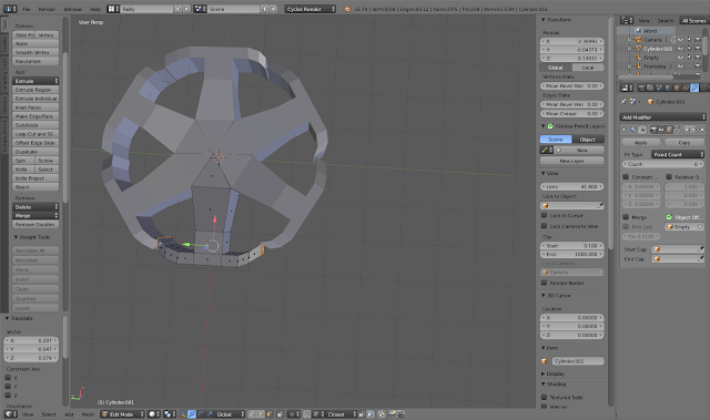
I created a cylinder
with 6 vertices to form a 6-sided cylinder. Then I split it up and deleted
all the other sides except for one. Then I set my 3d cursor to the center
where I want my other “pie” to be revolving around. I set my origin to the 3d
cursor and then created an empty ‘plane axes’. Then I select the
cylinder”pie” and add an array modifier and set iteration to 6. Then I took
the rotation empty plane and rotated it 360 degrees. I now have a 6 sided
flat cylinder. So all I did was just extrude the main “pie” and the rest
would follow. To create the tire metal rim, I just extruded until it almost
forms a circle and then I vertex snap the edges to make them all come
together.
|
|
 |
Cont'd
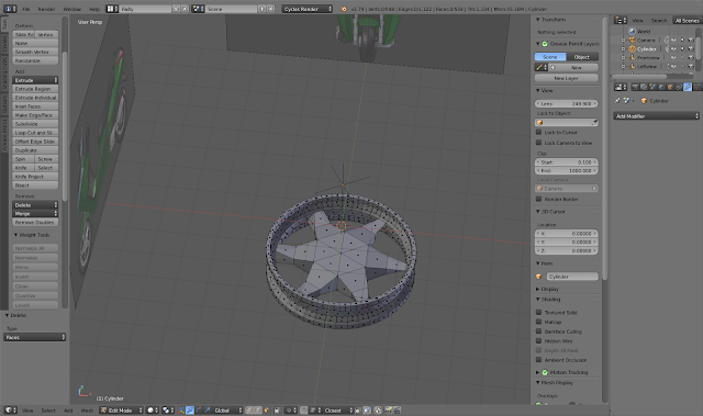
Whats left to do is
just highlight the rim faces(downside and upside) and go to tab on the left
and use “loop tools”>”Circle”
|
|
 |
Creating the wheels
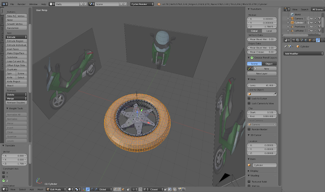
I created a Torus and
aligned it nicely with the metal tire rim
|
|
 |
Screw mechanism
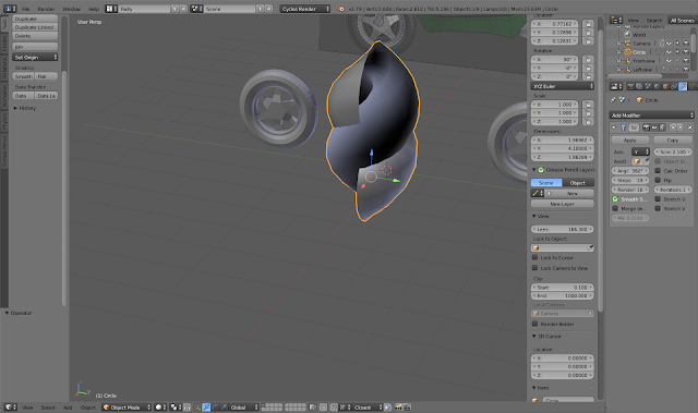
First I created a
circle mesh. Then I adjusted the vertices down to 18 and applied a “screw”
modifier to come to this stage. This is for the suspension cord.
|
|
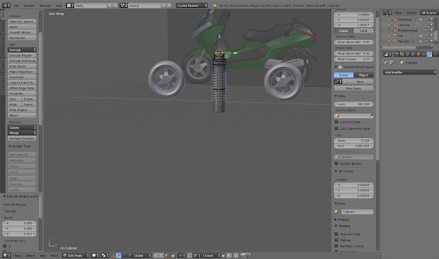 |
Suspension Cord with the metal bar
I then put the
‘iterations’ to 11 and change the axis to Y. And update the ‘screw’ value in
the modifier to make it look like a spring(closer together). All that’s left
now is to scale the circle head to make it thinner. I created a cylinder
within the spring and extruded the surfaces like in the picture. I then
extruded the bottom and made a curve and expanded the bottom
|
Exhaust & Gearbox |
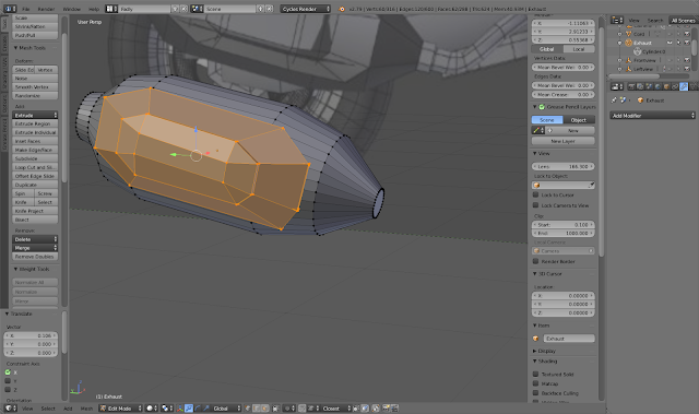 |
Exhaust pipes
I took a cylinder and
rotate it into position. I extruded the parts
of the cylinder by pressing e. And also I scaled them as and when I need to.to
form the shape in the reference. I also extruded the circular face at the other
end to form the long tube. From a cube, I made
loop cuts on the surface to form an octohedron shape. I then squished it and
made it more longer. In this last picture, what I did was to
loop select the top edges and scaled and extruded them to the example picture
here.I then attached it to the exhaust.
|
|
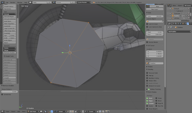 |
Gearbox1
Create a circle mesh
and turn vertices down to 8. Fit it according to the reference and then form
a face on the circle. Then we want to cut the circle, so use “J” and slice
the circle as shown here. Next, we want to use the solidify modifier to add
volume to the item.
|
|
 |
Gearbox2
I extruded the thing
according to the topology of the reference. I then duplicated the circle
extrusion and combined those together by removing doubles and setting it to
0.23. I then added a ‘solidify modifier at the back to make the plane
thicker.
|
|
 |
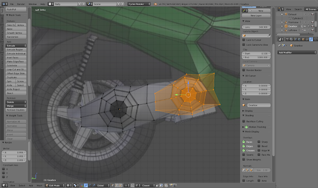
Gearbox3
Finally I made the
extrusion at the bottom into a circle by ‘looptools’>’circle’ under the
specials menu. I also adjusted the vertices on the sides to make it look like
a sloping item.
|
|
Main Motor Body
 |
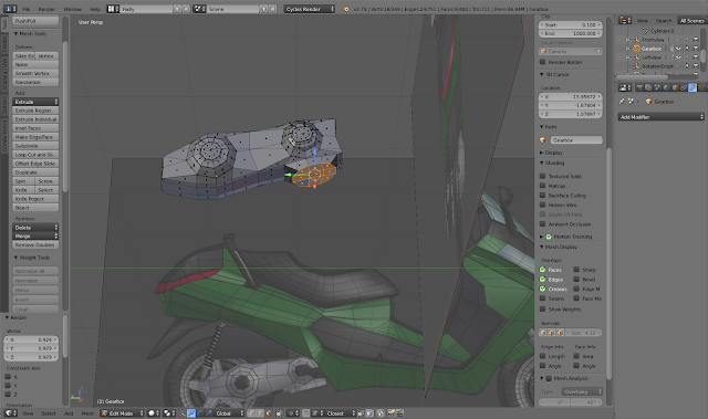
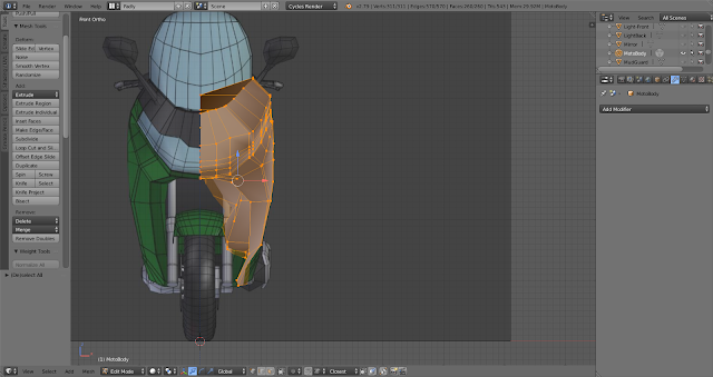
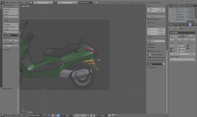
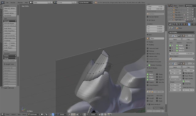
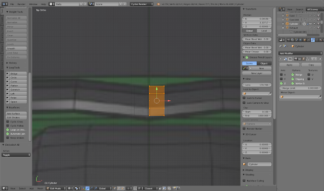
I started with a
plane and rotated it 90degrees to face me(sideview-right). I then adjusted
the vertices according to the lines shown. I decided to cover up all the
green areas of the body. For those vertices in between, I used “J” to connect
the vertices. I then subdivided the new edges according to how many vertices
I would need.
|
|
 |
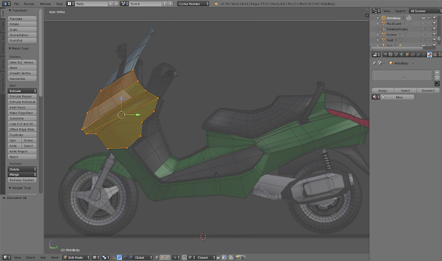
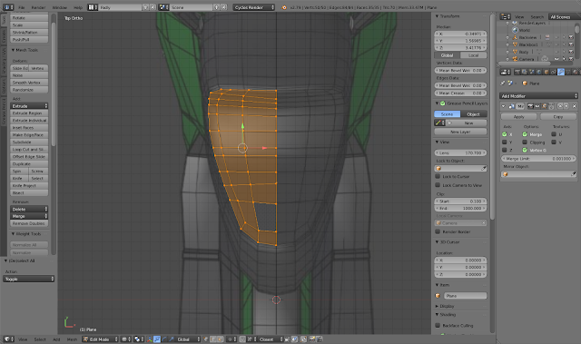
Then I extruded all
the vertices according to the topology of the bike. Did this by referring to
the top-view image reference. To do this simpler, from top-view, I select a
group of vertices to extrude out, then ‘pull it out’, then I “ctrl-“ to
lessen the area of influence and ‘pull it’, and so on, like a Chinese
lantern-like fashion.
|
|
 |
I applied the mirror
modifier before I went to model and join the “inner” black parts of the
vehicle. I connected the vertices by using “f” two by two. I cannot use “J”
as there are no faces yet. I then individually add a face to the vertices. Lastly,
I extruded the “black parts” inwards, just like the real motorbike.
|
|
 |
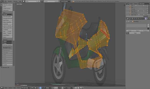
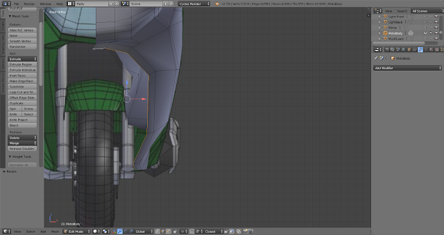
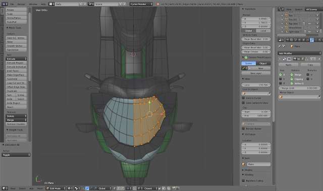
I switched to the
front view to continue follow the topology of the motorbike. I then extruded
the edges of the wheel hollow inwards(see picture, I also cancelled the
mirror modifier for now so I can see better).
|
|
 |
I did the same
extruding of the edges at the back of the vehicle to form the concave hollow
for the wheel.
|
|
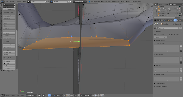 |
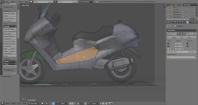
I then form a face on
the bottom of the motorbike and added edges and vertices(can’t apply edge
loops as not a 4-side figure)
|
|
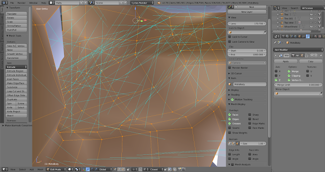 |
Lastly, I added the
mirror modifier again. I also inverted some normal so that all sides are
facing the front. And I turned on “Smooth” from the transform tab.
|
|
Connectors,Mudguard & Dirt Shield
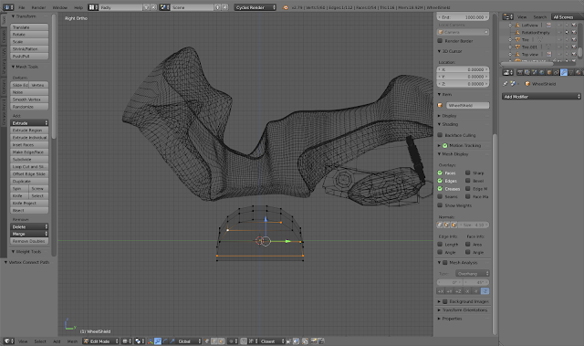 |
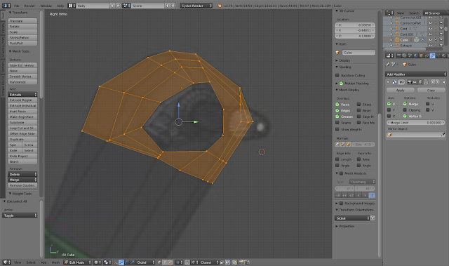
I made a cube and
bevel the sides to make a semi circle. I then cut the circle in half. I made
some vertices and then I contorted the shape to look like a wheel shield..(ignore the previous motorbike body in this picture)
|
|
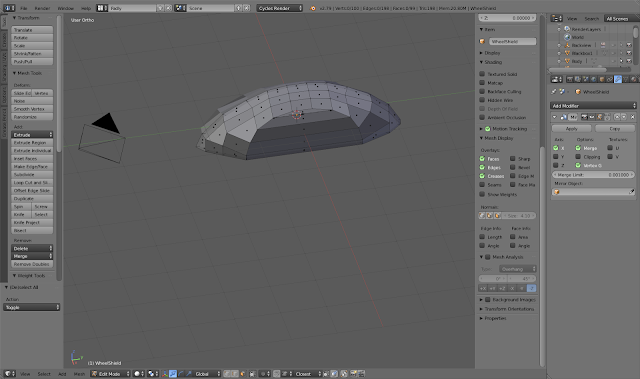 |
I then made the
surface smooth and position it
|
|
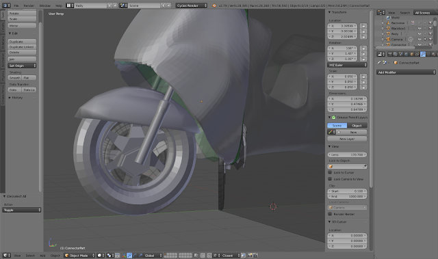 |
I created a cylinder,
scaled it smaller and extruded the different parts to look like a wheel
connector. The foot of the connector, I just created a circle, turn down the
vertices number and then contort it to look like that shape. .(ignore the previous motorbike body in the picture)
|
|
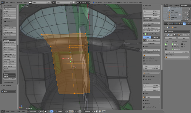 |
Mudguard1: So I made a plane
mesh and adjusted the vertices according to reference images using the top and right sided picture. I then cut
it into half and added mirror modifier.
|
|
 |
Mudguard2: I also adjusted the
vertices to cover the side, then I just smoothed the surface and added a
solidify modifier to thicker.
|
|
Seats, Screen, Side Mirrors
 |
Seat1: first created a
mesh plane and I adjusted the vertices to match the reference image. I then
cut the plane into half and use the mirror modifier.
|
|
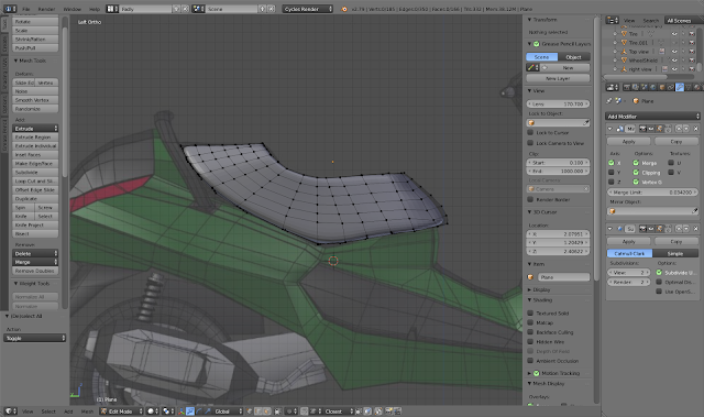 |
Seat2:Lastly I used
the solidify modifier to “thicken” the plane and transform it into a seat. I
then added edge loops and adjusted the vertices like in this picture. Once
done, I used the subdivision modifier.
|
|
 |
Screen1:I added a
plane mesh and adjusted the vertices according to the reference image. I also
used edge loops to contort the mesh equally. I then cut the plane into half
and added a mirror modifier.
|
|
 |
Screen2:I then added
a solidify modifier to make the screen glass thicker by abit. And finally,
like all my mirror modifiers, I adjusted until the centre line is not so
visible(using “merge limit”), as well as delete faces in between the mirrors.
.(ignore the previous
motorbike body in this picture)
|
|
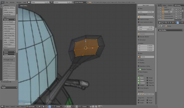 |
Sidemirror1: I
started with a circle mesh with 8 vertices and started to follow the topology
of the bike. I didn’t make the handle yet
|
|
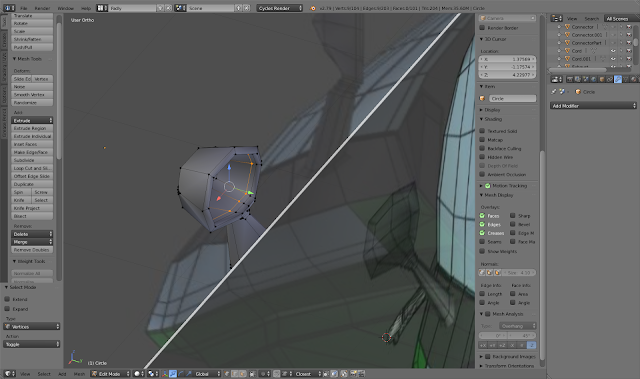 |
Sidemirror2:Once I
got the correct shape geometry from every angle, I procceded to add a solidify
modifier. At the base of the mesh where the handle is supposed to be, I added
a ‘specials’ loop tools circle and extruded the handle from there. In this
stage pictured, I added an edge loop to make the curvature significant and
then another one so that I can add a face inside for the mirror. I also made
sure normal are calculated outwards.
|
|
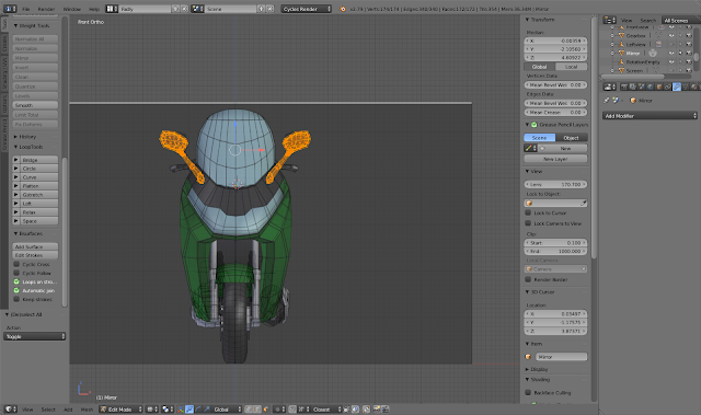 |
Sidemirror3:Once
happy, I then duplicated the mesh and move it along the x axis as well as I
pressed S to scale on the x axis to “-1”, which will mirror the mirror.
|
|
Dashboard & backhandle
 |
Backhandle1: I
started out with a cylinder with 6 vertices, then cut it in half and applied
the mirror modifier. I then began to extrude
|
|
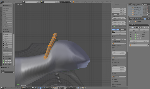 |
Backhandle2: I
extruded along the reference line(right and top images) and then attach the
bottom of the handle on the body. .(ignore the previous
motorbike body in this picture)
|
|
 |
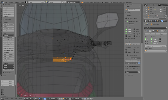
Dashboard1: I made a
cube and cut it into half with edge loop, deleted the faces of one side and
applied a mirror modifier. I then took two of the top edges and bevelled
them. I then subdivided the edge at the bottom and connected the vertices
through using “J”. The hard part comes when I tried to delete a face in the
middle to fit the handle and brake. Once done, I subdivided the edge to make
the shape shown in the picture. Then I extruded the vertices inwards twice.
Then I selected the inner vertices and use the specials(W) and looptools to make
it circular. This is the base of the handle.
|
|
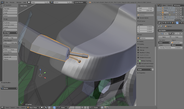 |
Dashboard Brakes: So
I subdivided one of the faces beside the handle and use specials(W) to make a
circle and extruded the brakes. I then added a sphere at the end.
|
|
 |
Smoothing: I then
used the backview image reference and extruded some parts of the bottom to
form this. I turned on ‘smooth’ from the transform tab and flip some faces
where their normal are wrong.
|
|
Textures & Materials
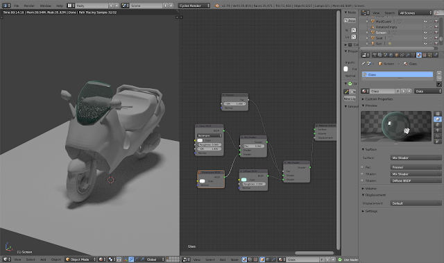 |
Acrylic Glass is made
first by adding a material on the bike screen and adding:
Glass bsdf,
Mix Shader1,
Mix Shader2(for translucence),
Fresnel,
Translucent shader,
Diffuse Bsdf,
In node editor,
attach the glass bsdf and diffuse bsdf to the mix shader1(and into output).
Then add Fresnel to the ‘factor’ of mixshader1, this allows the sides of the
screen to reflect light(set IOR to 1.49). Meanwhile adjust the color of the
diffuse bsdf to reflect acrylic green tint. Then add mixshader2 so that we
can combine a translucent shader, then turn down mixshader2’s factor to .049.
.(ignore the previous
motorbike body in this picture)
.(usage:
Screen(as shown).)
|
|
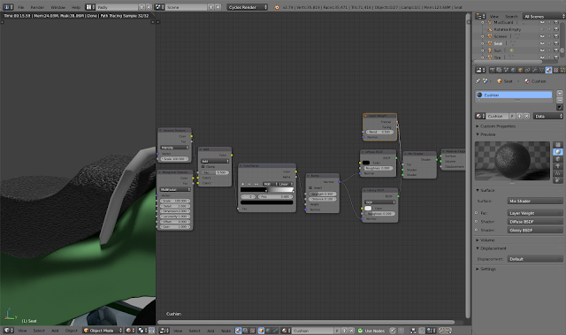 |
Cushion: I needed to make a
material with uneven texture. I added a:
· Glossy
bsdf
· Mix shader
· Layer
weight
To add gloss to the
material. The mix-shader is to combine the ‘diffuse’ with the ‘gloss bsdf’.
The ‘layer weight’ is added for the factor part of the mix-shader. Next, I
needed the bumps so I added:
· Voronoi
Texture
· Musgrave
Texture
· mixRGB
· ColorRamp
· Bump
‘Voronoi’ is scaled
to 100 to increase the “sediments” in the texture. ‘Musgrave’ is changed to
multifractal with a scale of 100 to make texture look “poped-up” and
‘sand-like’. Both these attributes are funnelled into the ‘mixRGB’ with the
“add” property. Then this info is funnelled into the ‘ColorRamp’ to create
more contrast in the texture. Change the gradient meter to black on one side
and slide it closer to the middle. Then funnel this into the ‘Bump’ and
change the strength to 0.3 and distance 0.1. Send the attributes to the
diffuse bsdf and the glossy bsdf.
.(usage: Seat
& Dashboard handle grips.)
|
|
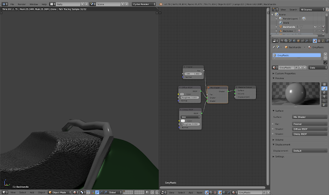 |
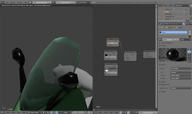
Grey Plastic: I needed
a glossy hard plastic material, I added these:
· MixShader
· Fresnel
· Glossy
Bsdf
I added a mix Shader
in-between the standard diffuse bsdf and the output. I changed the color of
the ‘diffuse’ to grey. I then added ‘glossy bsdf’ with roughness of 0.05 and
then added ‘fresnel’ with IOR of 1.46.
.(usage: Backhandle)
|
|
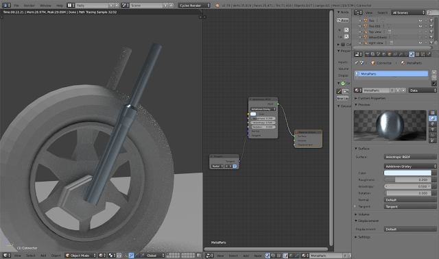 |
Metal: I deleted the
standard ‘diffuse bsdf’ in the node editor and added:
· Anisotropic
BSDF
· Tangent
I changed the
‘Anisotropic’ to Ashkimin-shirley and change the color to a coolish blue.
Like cold metal. I then adjusted the ‘Tangent’ so that the light falls
vertically on the metal.
.(usage: Wheel
connectors, Suspension, Exhaust & Gearbox)
|
|
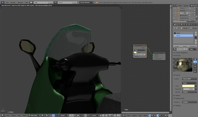 |
Mirror: I simply
deleted the standard ‘diffuse bsdf’ and replaced it with the ‘Glossy bsdf’. I
changed the attribute to “Sharp” and color to a slight yellow tint.
.(usage:
Sidemirror interior)
|
|
 |
Black Plastic: Like
the grey plastic, I simply added Fresnel(IOR 1.46) and Glossy bsdf(roughness
0.05) into the mix-shader. The ‘Diffuse bsdf’ is changed to black and
funnelled into the MixShader.
.(usage:
Sidemirror,Some parts of the Motorbike body)
|
|
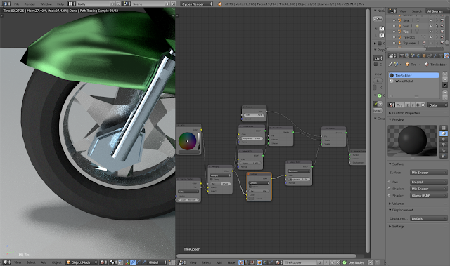 |
Rubber: So I added:
· RGB
· Voronoi
Texture
· MixRGB
· Fresnel
· Velvet
BSDF
· Lighten
· Glossy
· MixShader1
· MixShader2
I change the ‘RGB’ to
be a light black color. ‘Voronoi Texture’ is added with “Cells” property and
scale set to 500. Next, funnel these attributes into a ‘MixRGB’ and change
attribute to “Multiply”. Then output it’s color unto ‘diffuse bsdf’, ‘velvet
bsdf’(Sigma is 1) and ‘lighten’(Factor is 1). I then added a ‘fresnel’ with
IOR 1.519 and sent it to both the mixshaders. The ‘diffuse’ and ‘velvet’ is
output to MixShader1, which in turn is sent to MixShader2.The
lighten>Glossy bsdf(roughness 0.15) is output to MixShader2.
.(usage: Tires)
|
|
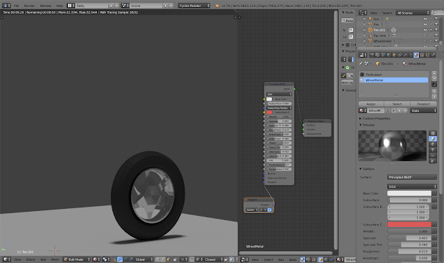 |
White metal: For this
I just added:
· Principled
BSDF
· Tangent
I deleted the
standard ‘diffuse bsdf’. I changed the tangent to ‘Z’ axis. At ‘Principled
BSDF’, I made the changes as shown in the picture.
.(usage: Wheel
interior, Exhaust shield, Dashboard Handbrakes and griptip and gripbase,)
|
|
 |
Cables & Springs:
I simply changed the ‘diffuse bsdf’ to purple.
.(usage:
Suspension spring)
|
|
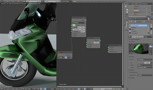 |
Chrome:I added these
to make the chrome body and the wheelshield.
· Tangent
· Anisotropic
BSDF
· MixShader
I changed ‘Tangent’
to X axis. I also changed the ‘Anisotropic’ attribute to “Beckmann” with
roughness of 0.35, Anisotropy of 0.6 and rotation of 0.622. I then funnelled
it into the ‘MixShader’ and into the output.
.(usage:
Motorbike Body & Wheel Shield)
|
|
UV Mapping & Lighting
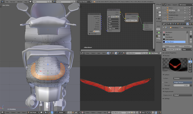 |
UVMAP-Backlight: I
highlighted the faces where the backlight is then press “ctrl+e” and mark
seams. Then I pressed “U” and instead of unwrap, I chose “Project as viewed”.
Once done, I went into ‘uv editor mode’ and placed the vertice points onto
the png image of the lighting that I grabbed from the real model.
I also needed to
create a new material and went into the ‘node editor’ and deleted the
standard ‘diffuse bsdf’ and instead added the ‘Image texture’ and opened the
same png file of the backlight. I then added:
·Texture
coordinate
·Emission
The ‘Texture
coordinate’ is connected to the ‘image’s Vector. All this is funnelled into
the ‘Emission’ and strength is turned up to 0.56, so as to make the light
glow.
.(usage:
BackLight Beam)
|
|
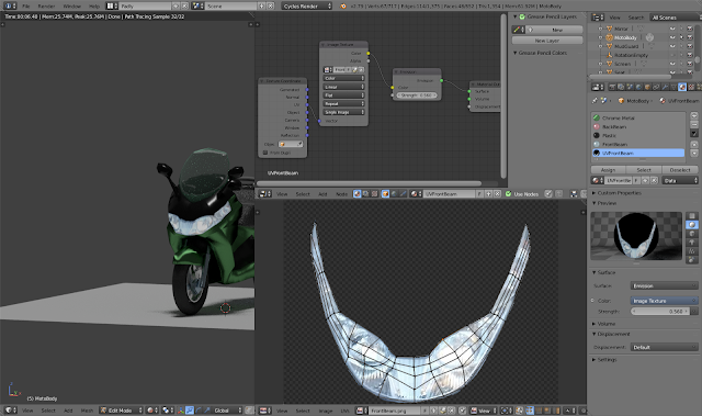 |
UVMap-Frontlight:This
process is the same as for the backlight. I made sure to create a new
material and just changed the image that is to be mapped.
.(usage:
FrontLight Beam)
|
|
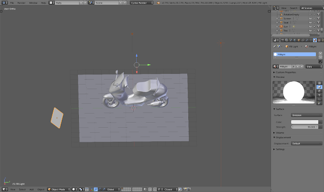 |
I added a Keylight(Plane mesh with
emission strength of 39), a fill light(Sun) and a rim light(Spot). The latter
has a blueish tint to the lighting and is place on the other side of the
motorcycle. (I changed the naming to “KeyLight” for the
emission later on)
|
That's It. That's how I got to model the piaggio X8!
© 2019 Fadly.M.H.Wychowvski


No comments:
Post a Comment